(Late Summer 2019)
I wrote previously about my successful animatronic eyes build using some ping pong balls as ’eyes’, which moved around on a rig, each powered by 2 servos, for 2 axes of movement and controlled by an Adafruit Crickit and the Circuit Playground Express [CPE].
It worked well enough and the effect was quite interesting, but for what I wanted - eyes moving in a hood as party of a creepy monster animatronic for Hallowe’en - there were a few drawbacks. I could put the Cricket/CPE behind the eyes and use the onboard LEDs to shine a creepy red light behind them which looked good, but it was difficult to see them under most hood ideas. Also, I could program the ’eyes’ to move in a nice creepy way, but the servo noise was a bit distracting.
So I went looking for an alternative and ended up at the disastrous money sucking venue (in a good way) which is Adafruit.com, and decided to build out the two LCD panel ‘Snake eye’ project which seemed to fit the bill.
It doesn’t consist of physical eyes of course, which was my original goal, instead it being IPS LCD panel based. However, this would address two issues: it would mean I could place them under any hood as they’d be more easily visible, and also there’d be no noise.
I also had a plan to re-use those servos as part of a simple hand animatronic. More on that to come.
Moving on. I ordered the kit from Adafruit and I have to say, I find shipments from Adafruit all the way from New York to here in Japan to be very prompt, and they always seem to do a tidy job getting all the parts into the smallest box they can.
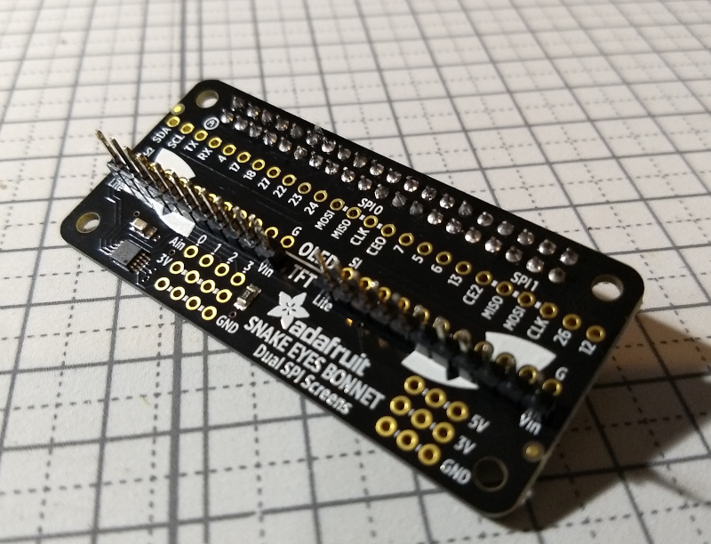
The kit is based on a Raspberry Pi Snake Eyes Bonnet which uses the Pi’s GPIO pins, which I’ve had quite a bit of experience with from some previous projects, including the wifi robot car I’d built a few years ago.
The project comes with the two 240x240 pixel IPS LCD screens which need to be soldered to a ribbon cable and in turn soldered in to the bonnet, which then plugs into the Pi, which in turn runs the code.
Simple, right? This is outside of my usual builds, but I felt pretty confident since my soldering isn’t bad, and the Adafruit project sheets usually cover most scenarios.
Off I went. The documentation is pretty good, but there had also been a revision to the LCD panels since the documentation was written, meaning there was an extra pin out to account for. Not difficult to figure out, so I soldered it all up, brought out my multimeter, checked the connections, and all seemed good, so I plugged it all together.
Next up, install a core Raspbian OS install to a spare SD card, install the Snake Eyes software, which is broadly a video driver and some code to generate the eye patterns on each. After I got it all built to spec, I plugged in the two eye screens to the bonnet, then the Pi to my monitor and booted it up.
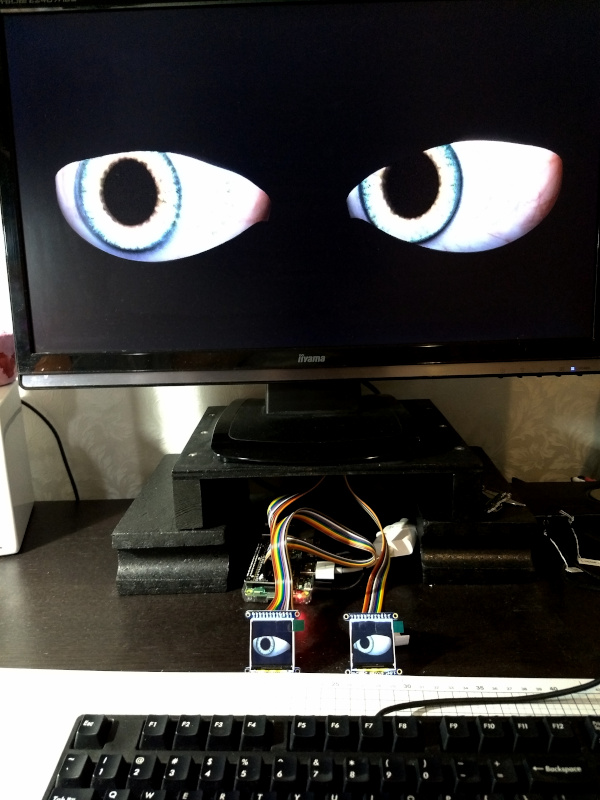
On my main monitor were two creepy eyes looking around. Success! However, only one of the LCD screens had an eye. The left eye screen specifically. Well that was disappointing.
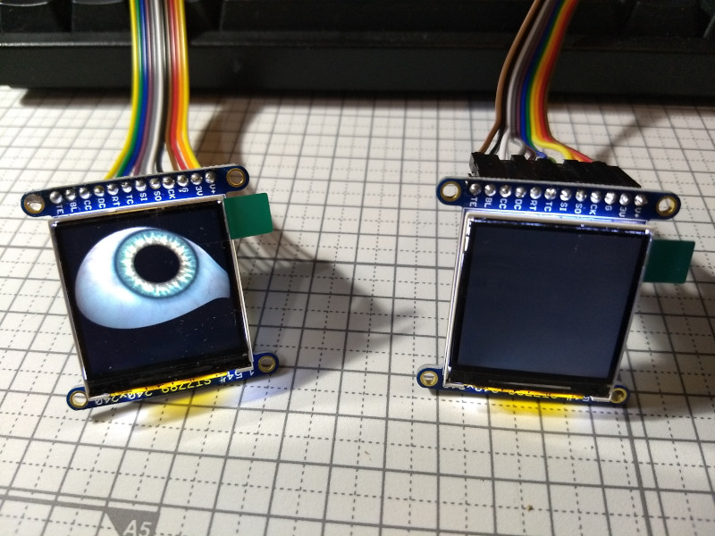
I then disassembled it all and re-assembled it. Same issue. I considered one of the eye screens could be defective, so I swapped them over, but the screen originally on the left was still the only one working, so there was a good chance both screens were actually fine.
I got the multimeter out again, suspecting a bad solder. They all appeared fine, so I also ordered another bonnet, thinking somehow the one I had was broken, since I knew the Pi was fine.
Next stop was to ask on the forums, to see if anyone else had seen this issue. I waited a week and nothing. A bit disappointing, so I posted in another area of the site, and finally got some traction. That’s a good reminder to be very sure you’ve posted correctly and not give up when no one initially responds.
A good thing about the Adafruit forums is that once you do get some movement on a thread, people seem very keen to help out.
An Adafruit_support person picked my thread up and we got down to business. First thing to check as with any hardware project like this is the components and connectors - specifically the solders, so I posted a photo of my bonnet and LCD connecting solders. All good. In fact, the admin said ‘Your soldering looks excellent, so I doubt there are any connection problems in the joints.’ I’m going to print that out and have it framed on the wall. We then continued swapping parts to see how or if the problem transferred. All seemed good - they even part refunded my new bonnet order, though that proved to be fine too.
So the hardware, despite being a likely culprit actually seemed fine, so time to move over and look at the software side of things.
I’d been looking on the rest of the Adafruit forums for anything which looked like it could point the way, and of course in the project build document itself, in case I’d missed something there. It didn’t seem so, but some of the ideas in there would come in to play later.
I went back to the base Raspbian OS build, and tried a newer version than recommended. It didn’t work, so I went back to my initial install - the benefits of an OS on a simple SD card!
Fortunately another forum user had seen something similar, and had resolved their issue by deleting a line from their rc.local file. This file helps with running things when the Pi boots with runlevels, but in this modern days of systemd based distros, this is being deprecated. What user elbrujo found was that they could get an image on both LCDs by commenting out the line /usr/local/bin/gpio-halt & which I think relates to continuing signal on the GPIO board, described on this Github page.
Following the edit and a reboot, lo and behold, the left panel now worked, but the right panel had a scrolling image, like old CRT TVs with a vertical hold issue. Fortunately, this kind of issue was covered in the install guide and is related to the video bitrate sent to the panel, and is dependant on the type of panel and likely Pi being used, so fixing it was a question of trying a few different values in one of the config files, et voila, snake eyes now perfectly functioning on both IPS LCD panels (and HDMI).
For me, this was sudo ./fbx2 -i -b 13000000.
So that’s a positive ending to the story, and justifies the time put in on the forum, which are generally very good, both with the official support people, and other users, despite that initial post which went nowhere.
To follow up, there is another thing to look out for. After the work I put in to get this working, I took a copy of the SD card, and kept it on my archive server, which was very useful, since an apt update run about six months later somehow broke it again. I’ll try to find some time to see why that was, but it is important to remember that some of these projects are built to specific hardware/OS/code versions, so once you get it working, it’s worth taking that backup.